Metso Insights Blog Mining and metals blog High intensity air injection spargers - the fundamental technology in column flotation
Mining Metals refining
Dec 19, 2017

High intensity air injection spargers - the fundamental technology in column flotation

Sparging technology has evolved significantly over the past three decades, progressing from simple pipe systems to systems that include automatic slurry backflow protection. In this article we examine the different types of sparger technologies available and the most important factors to consider when choosing the most suitable air sparging system for your column flotation process.
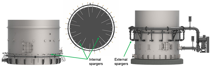
Internal and external spargers
Figure 1. Internal and external spargers.

Since the flotation process is interaction between particles and air bubbles, the greater the concentration of hydrophobic particles and available air bubble surface, the more effective the process. In practical terms, the concentration of particles is limited to the maximum viscosity that allows a homogeneous distribution of ascending bubbles at a uniform rate and to the maximum acceptable hydrophilic entrainment in the froth. In turn, the amount of air is limited to the maximum flow rate that still provides a homogeneous distribution of rising bubbles without excessive turbulence and bubble collapse.

In order to optimize flotation for a specific aeration rate, the air sparging system must produce small bubbles. The small bubbles provide higher surface area, which is favorable for flotation kinetics. This effect has been shown in several studies. (Finch and Dobby, 1991; Gorain, 1997; Zhou, 1997)

In the past few decades, the main evolution of column flotation technology has occurred in the development of new sparger systems. Sparger systems are essential in pneumatic flotation since both aeration and particle suspension depend on them.

The main criteria to be considered when developing or choosing spargers are:

  • the ability to generate appropriate air dispersion with small bubbles that will promote the desired flotation performance
  • the reliability of operation, in order to guarantee that performance is consistent and stable
  • the ease of maintenance, in order to reduce operation costs; this aspect involves regular inspections/calibration on site and the possibility to remove spargers for maintenance without interrupting column operation
  • the ore features, especially particle size, in order to determine the best system for the application in question

Sparger types

Column spargers can be classified according to either their position in the column or the phenomenon involved in bubble generation. In terms of position, they are classified as internal if they are inserted into the column, or external if they are assembled outside the column tank.

In terms of bubble generation principles, most commercial spargers for columns create bubbles either by cavitation, or by direct injection of air (jetting).

Jetting

In jetting techniques, air is injected into the column at high velocities and bubbles are formed by the intense shear of the air jet with the pulp (Finch, 1995). The higher the intensity of the air injection, the higher the number of bubbles and the smaller their size.
In the past, the simplest way to inject air into a column using jetting corresponded to a pipe with a small orifice at its extremity or with several small orifices along its length. These pipes were inserted into the column and compressed air was injected through them. These types of spargers were used in several of the first industrial columns introduced in the 1980s, and some columns still have this type of system in place. The main issue with this simple pipe system was clogging. If there was an unexpected failure in compressed air supply, pulp flowed back from the column into the sparger pipe. This slurry caused clogging or internal wear in the sparger, damaging its ability to generate small bubbles and, consequently, impairing column performance. In almost all cases, it was necessary to interrupt column operation to replace the spargers, reducing flotation availability.

Sparger technology has developed significantly since the introduction of these first simple pipe systems. Although the first sparger design with automatic protection in case of air-supply failure was developed in the 1970s, this system suffered problems with wear. The concept of automatic closing was further developed in the 1990s. In 2016, Outotec introduced the SonicSparger Jet. With this technology, the optimal air pressure, airflow rate, and orifice size are determined in order to achieve the most appropriate air injection, with sonic velocities.

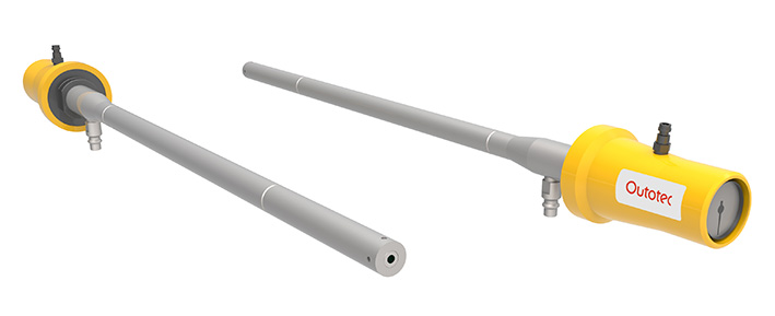
Outotec SonicSparger Jet
Figure 2. Outotec SonicSparger Jet.

The SonicSparger Jet is reliable and easy to control. It is designed to close automatically in case of an unexpected shutdown of the main air source, preventing the backflow of slurry into the sparger. In contrast to other systems, SonicSparger Jet has a unique back-pressure chamber that uses compressed air to ensure that the sparger outlet opens only when the main airflow reaches a pressure higher than 2 bar, which is sufficient to avoid slurry backflow. A gauge indicates this control pressure in the chamber.

Furthermore, the SonicSparger Jet can be removed from and inserted into the column without interrupting operation.

Venturi – Cavitation

The attachment of fine particles (fines) to bubbles is more difficult because the particles are lighter. Instead of attaching, i.e. rupturing, the interface of water surrounding the bubbles and making contact with the air, fine particles tend to follow the liquid streamlines around the bubble.

The flotation of fines can be improved by creating a larger number of small and more energetic bubbles in order to increase the probability of collision.

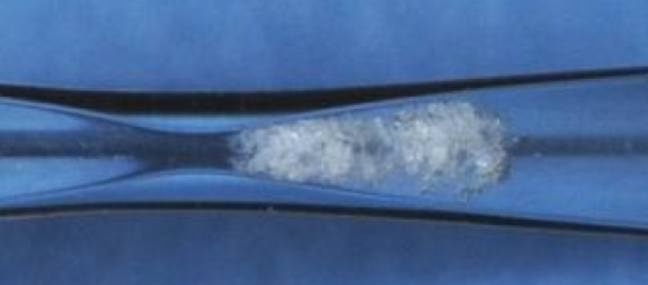
The cavitation phenomenon is the best way to generate nano and microbubbles for flotation. Among the different forms of promoting cavitation, the best way to create the bubbles of the smallest possible size is by using a Venturi tube. Venturi tubes comprise a constricted section, typically centralized within a pipe, after which the tube gradually returns to the original diameter.

Bubble generation through cavitation
Figure 3. Bubble generation through cavitation.

In fluid dynamics, a fluid's velocity increases as it passes through a constriction, while its static pressure decreases. When the pressure decreases locally below the liquid vapor pressure, voids full of vapor, or microbubbles, are created as a result of the balance of pressures. These microbubbles also incorporate dissolved air. This form of cavitation is able to provide the smallest size distribution of bubbles, smaller than static mixers (Xiong and Peng, 2015). It has been demonstrated that Venturi tubes also provide better results in flotation. (Zhou et al., 1997)

Besides vapor and dissolved air, bubbles can also be generated using air injection. In this case, air is either introduced before cavitation constriction or aspirated through an opening in the constriction section, where the pressure is lower than the external pressure.

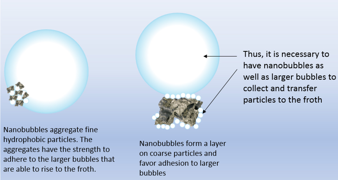
There are several different concepts describing the effects of nanobubbles in flotation. One of them is that nanobubbles aggregate fine hydrophobic particles, and these aggregates have the strength to adhere to larger bubbles that are able to rise up to the froth. Nanobubbles form a layer on coarse particles and favor adhesion to larger bubbles. Thus, it is necessary to have nanobubbles as well as larger bubbles to collect and transfer particles to the froth. (Zhou, 1997)

Effect of nanobubbles in flotation
Figure 4. Effect of nanobubbles in flotation.

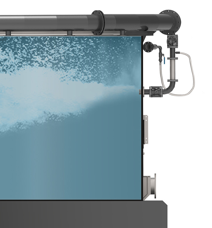
When this system is installed in flotation columns, the underflow pulp of the column is first pumped into a manifold and then back into the column, passing through a pipe where there is an injection of air, and then to Venturi spargers.

Typical installation of Venturi spargers
Figure 5. Typical installation of Venturi spargers.

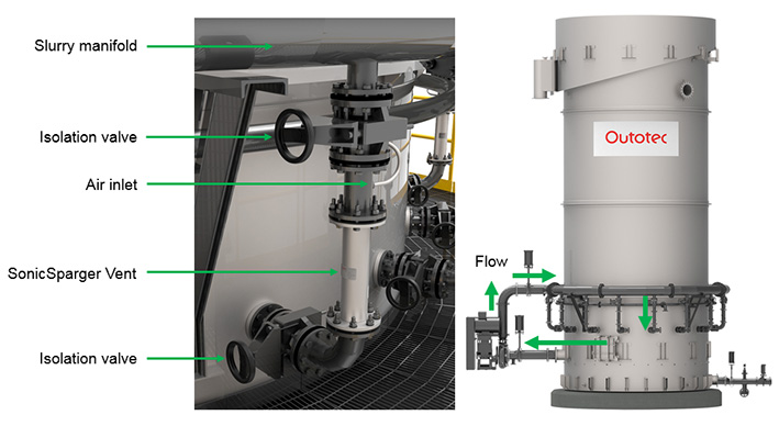
The Outotec SonicSparger Vent has been designed with the optimal angles for ensuring a longer life for the smallest bubbles, which minimizes bubble disruption after the constriction. The design is based on recent studies of Venturi tubes applied to flotation, in which results were evaluated primarily in terms of flotation performance, but also based on bubble size distribution. The Outotec SonicSparger Vent also features an extended internal ceramic nozzle to minimize wear by abrasion, guaranteeing a longer life for the sparger.

Outotec SonicSparger Vent
Figure 6. Outotec SonicSparger Vent.

The Outotec SonicSparger Vent has been designed with the optimal angles for ensuring a longer life for the smallest bubbles, which minimizes bubble disruption after the constriction. The design is based on recent studies of Venturi tubes applied to flotation, in which results were evaluated primarily in terms of flotation performance, but also based on bubble size distribution. The Outotec SonicSparger Vent also features an extended internal ceramic nozzle to minimize wear by abrasion, guaranteeing a longer life for the sparger.

Application

The selected sparger type will depend on particle size, ore type and, sometimes, on the specific demands of a particular project. In general terms, the Outotec SonicSparger Vent tends to be more appropriate for fine particles (below 44 µm) because the benefit in terms of the recovery of fines tends to outweigh the extra cost of the recirculation pump. The most appropriate system should be selected on a case-by-case basis in order to optimize costs and benefits.

References

Finch, J., & Dobby, G. (1991). Column Flotation. Pergamon Press.

Gorain, B., Franzidis, J., & Manlapig, E. (1997). Studies on impeller type, impeller speed, and air flow rate in an industrial scale flotation cell—Part 4: effects of bubble surface area flux on flotation kinetics. Minerals Engineering, 10, 367-379.

Xiong, Y., & Peng, F. (2015). Optimization of cavitation venturi tube design for pico and nano bubbles. International Journal of Mining Science and Technology.

Zhou, Z. H. (1997). Role of hydrodynamic cavitation in fine particle flotation. Int. J. Miner. Process, 139-149.

Mining Metals refining